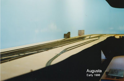
Over several months work progressed very well and with a good supply of Micro Engineering weathered Code 55 track and their newly released Code 55 #5 turnouts we started to rough in the track plan for the intermediate towns.
During our visit to Portland in 1994 Vic and I both commented on just how high tracks are and just how well groomed the ballast was on all of the mainlines we had a chance to see. This stuck in my head when I was thinking about how best to replicate this in the new layout. I decided that when cutting the sub-road bed out of the C grade 5 ply that I would make it just wider than normal to allow me to get the correct ballast profile and add drainage ditches where possible. These are seldom modelled and do help to make a layouts track work look better. With the road bed cut and fitted it was time to lay the cork. Sheets of 3 mm and 2.5 mm cork were purchased that would be then cut into strips to make live a little easier. I decided that to obtain the look of the track that I wanted I would lay to layers of cork for the mainline by using two 3mm strips one top of one another. The first layer was made by laying two strips side by side along the centre line of the track plan. These were cut to give an overall width of 16 feet. The top layer was cut into 9 foot widths the length of the cross-ties and laid directly down the middle of the first giving me a total height of 6 mm. The passing sidings were done in a similar fashion but using two layers of 2.5 mm cork for a total height of 5 mm. Then for all of the industrial tracks and main yards I used just one layer of 3 mm cork. The track was clued down using clear silicone being careful not to apply too much so it did not ooze up between the ties. This process worked very well and by not having to drill holes and pin the track it looks so much better. (nowadays I use Caulk as it is easier to use). The first lot of ME turnouts were a bit of a disaster as the frog casting was cast too high meaning I had to file them flat and file the depth of the rail for the flanges not to bottom out. When fitting these I used as little silicone as possible and pined each end before lining them up with the rail using a 3 foot steel rule and making sure that they were very straight as they had a tendency to be bowed in the middle. I chose to used the ME insulated rail joiners at that time as they were nice and small.
 |
| The grey building is a Walthers cool storage cut in half and modified. |
Good progress was made in under four years, trains were running however industries were still being sorted as to what goes where and why.
More later.
Rod.


No comments:
Post a Comment