30/01/2013

Let's travel over the layout


Lets travel over the layout as the scenery is detailed.

     Thanks for dropping by. As mentioned I wanted to get a base of scenery down and then do the detail work next. Getting the correct buildings in place took more time than I first thought however it is worthwhile just taking your time to get the feel of the area just right.

     So here are some more completed scenes. We have moved forward quite a bit as these images are from 2005 / 2006.


This is the underpass at the right hand end of Augusta. Udall is to the right

The SD40-2 that I painted is heading to Augusta after just passing beneath the overpass at the junction
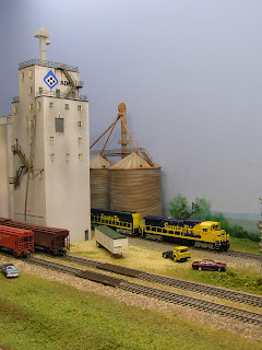
This shot was taken before the piping was added to join the bins to the elevator behind the Udall elevator
     Well that's it for another day thanks for dropping by.
     Rod.

27/01/2013

The journey Continues


Continuing the journey of the construction of the SFRSD

     A few more images of the early stages of the railroad.
The very early stages of the town of Ponca City

And the development of Red Rock. here you can see the narrow sub-road bed.

The new culvert between Red Rock and the original site of Guthrie before the layout was extended


And Flynn the second of the yards
Over the next few posts I will start to show the detail to the scenery and towns.
That's it for today, thanks for stopping by again.
Rod.

21/01/2013

More scenery


More early scenery on the SFRSD

     As mentioned in earlier posts I wanted to get a scenery base completed just to make it feel more like a real railroad. These are more images from my early days during construction of the SFRSD.

A view down the start of main street at the East end of Winfield
This is a view from the East end of Hackney of very early work being done to place buildings
A closer look. The small building in the middle was scratch built from an image I took at Ransom Ill.


 As I enter these images in this and earlier posts it is hard to realize the changes that have taken place to the whole railroad.
That's it for another day, thanks for stopping by.
Rod.

20/01/2013

Scenery moving ahead


Scenery moving ahead.

     Last post I talked about the track at Augusta and the bridge over the Wichita River, so lets take a look at the progress in other areas. This scenery was really just a basic layer so that in time I could return and try to give it a bit more oomph. One of the best things to happen in the modeling fraternity in the early 1990's was finding the new super trees sold by Scenic Express. I was fortunate enough to get a large box of these during a visit to the San Jose N Scale Convention from Bragdon way back and got over 300 trees made out of this initial box full. Well worth putting in some time making your trees with these as they come out looking very good.
     In the late 1990's there was not the range of buildings available as now so went down the path as many have and purchased the standard range of Walthers kits. One of these was the Medusa Cement Plant. I did a bit of work to it by cutting out one of the doors below one of the silos and added some detail to the roof. It also got a shot from my air brush.

The Winfield ready mix plant is on the East end of Winfield
     This building lasted here for many years until one of my friends could not locate one for his layout just a few years back. I decided I wanted something different so off it went to John's layout where it sits very comfortably in his town of Etter.
     As I mentioned my scenery was very basic so here are just a few pics of what it looked like back in 1999 / 2000.

 
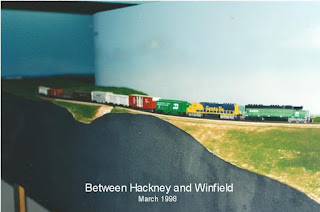
Between Winfield and Hackney by the way the track is super elevated on all of the corners

From Hackney West end under the backdrop heading to Ponca City

The small culvert between Red Rock and Perry.
     Notice the trailing Geep has been modified by the addition of the smoke deflectors along the side and on the roof. It also got a shot of paint from my airbrush into another Kodachrome unit.
That's it for now catch you later.
Rod.

16/01/2013

Continuing the build


Continuing on the build

     Now that all of the track was down and the layout wired it was time to start on the scenery.

The loco storage is to the right with the caboose track beside it
This is how the town of Augusta finished up looking. The track to the left is an interchange track.
     I enjoy the construction side of layout building however I enjoy the scenery and scratch building even more.
     I decided that I wanted to use a different scenery product so whilst wondering around at a local train show I came across a product called Carrs. This is an English model supply company that I had not seen before. I purchased several small plastic bags of various shades of their ground foam. It is much finer than the Woodlands ground foams I had used previously and blended together very well. So after applying a wash of colour to the plaster I set about laying some foam. It was important that I had the lighter colours on the higher sides of the small hills with the darker colours on the low side and in the valleys as this is were water gathers and the grass is much healthier.
     My friend Vic assembled and made some modifications to a Micro Engineering bridge kit for the bridge over the Washita River and supplied the cast plaster bridge abutments. While Vic was building bridges I was scratch building the Fitzpatrick Plastic Plant for Winfield. This was an article that was featured way back in Model Railroader with the plans drawn for HO. I used several sized thicknesses of styrene, Slater's embossed brick styrene (another English company) and electrical conduit for the bulk storage bins. For the tapered lower portion of the bins I used a casting resin in a very small funnel and by first giving it a coat of Vaseline I was able to remove the castings quite easily.

Work underway fitting the Washita River bridge


My Scratch built Fitzpatrick Plastics facility

     In 1999 we were underway but a very long way to go.
That's it for today stop by again.
Rod.

13/01/2013

Progress Continues


Progress continues.

     As you would have seen from my last post some small amounts of scenery were being done as we went along laying track, (had to keep the motivation up somehow). The base for the scenery was hi density blue foam. This came in sheets 2 foot x 8 foot and back then was very cost effective. This material was easy to cut and profile so to me it was a no brainer. At most of the areas between the towns the material was cut to fit the area and clued on from under the track sub-roadbed. I did this so we could build up the scenery and use the step that this created to add the drainage ditches that I wanted to have in the scenery along the track. Once this had dried then more foam was cut to shape and glued to the top to give the scenery the desired profile. Lots of rasping and then a layer of plaster impregnated gauze was added all over the foam. This provided a good base for my scenery.


My Friend Vic made this underpass and it was put between Augusta and Udall to help add distance between the two
     The Kato loco you see was modified by removing the original radiators and then adding a Bachmann U36 radiator section. I then painted it in the Santa Fe, Southern Pacific pre-merger scheme commonly termed Kodachrome.
That's probably enough for today so until the next post thanks for stopping by.
Rod.

11/01/2013

Back to construction

Back to the construction of the SFRSD

     Over several months work progressed very well and with a good supply of Micro Engineering weathered Code 55 track and their newly released Code 55 #5 turnouts we started to rough in the track plan for the intermediate towns.
     During our visit to Portland in 1994 Vic and I both commented on just how high tracks are and just how well groomed the ballast was on all of the mainlines we had a chance to see. This stuck in my head when I was thinking about how best to replicate this in the new layout. I decided that when cutting the sub-road bed out of the C grade 5 ply that I would make it just wider than normal to allow me to get the correct ballast profile and add drainage ditches where possible. These are seldom modelled and do help to make a layouts track work look better. With the road bed cut and fitted it was time to lay the cork. Sheets of 3 mm and 2.5 mm cork were purchased that would be then cut into strips to make live a little easier. I decided that to obtain the look of the track that I wanted I would lay to layers of cork for the mainline by using two 3mm strips one top of one another. The first layer was made by laying two strips side by side along the centre line of the track plan. These were cut  to give an overall width of 16 feet. The top layer was cut into 9 foot widths the length of the cross-ties and laid directly down the middle of the first giving me a total height of 6 mm. The passing sidings were done in a similar fashion but using two layers of 2.5 mm cork for a total height of 5 mm. Then for all of the industrial tracks and main yards I used just one layer of 3 mm cork. The track was clued down using clear silicone being careful not to apply too much so it did not ooze up between the ties. This process worked very well and by not having to drill holes and pin the track it looks so much better. (nowadays I use Caulk as it is easier to use). The first lot of ME turnouts were a bit of a disaster as the frog casting was cast too high meaning I had to file them flat and file the depth of the rail for the flanges not to bottom out. When fitting these I used as little silicone as possible and pined each end before lining them up with the rail using a 3 foot steel rule and making sure that they were very straight as they had a tendency to be bowed in the middle. I chose to used the ME insulated rail joiners at that time as they were nice and small.


The grey building is a Walthers cool storage cut in half and modified.


      The weathering on the M.E. rail was a huge issue initially as we could not solder the droppers to the rail. Once we realised that we needed to remove the weathering back to bare metal to enable us to solder we were under way (ask me how I know this). We used an English brand of liquid flux called Carrs with very fine rosin cored solder and it turnout well, we just needed to ensue that it was cleaned well after soldering as it is quite corrosive.
     Good progress was made in under four years, trains were running however industries were still being sorted as to what goes where and why.

More later.
Rod.


08/01/2013

DC Throttles

DC Throttles

     I mentioned in my last post that there were throttles hanging beside my control panels, today I thought I would let you know a little about them.
     One of the newer members of Melbntrak Model Railway club back in 1988 /89 Jim was a very accomplished computer technician and more than capable with model railroad wiring as well. Jim built for me a very well constructed 5 amp transformer (that never failed) about the size of four house bricks and weighed almost as much. Of course this was long before the range of wall warts now available. He also designed a small throttle that would work on the N trak modules and could very easily be adapted to work on my new SFRSD layout.
     The hand held portion consisted of only a pot and a reversing switch encased in a small plastic box connected to the layout via 5 core CB radio flexible cables. The guts of the system were built to fit neatly out of the way under the layout adjacent to where the throttle was to be used.

The section of the drawing on the left is the hand module.
     Once Jim had given me a parts list that would make 10 throttles it was just a matter of taking a trip to the radio shop and acquiring the parts.
     I am very fortunate to have a group of friends who enjoy working on one an others layouts. In this instance Ron and Greg both have telecommunications backgrounds and so were very eager to assist in putting all of these parts together. So one Saturday afternoon as I did work preparing wires etc Ron and Greg were sitting below the "L Girders" on very small seats making small P.C.Boards on which to mount all the bits. In no time flat these little units were made and connected to the transformer and the hand modules with very few issues. One of the nice touches that I did not find out about until 2009 when I converted to D.C.C was that the guys had signed and dated each one. Nice touch guys, loved it.
     These throttles lasted and performed flawlessly at all of my operating sessions up until 2009 when I changed to D.C.C. Their simple design allowed us to run D.C. for years without giving any problems. Thanks to Jim, Ron and Greg.
Thanks for stopping by.
Rod.

06/01/2013

Work continues


Work Continues.
  
     I will continue to show as many progress shots of the construction process as I can. We were limited with cameras in those early days and any digital shots taken where usually friends who had borrowed digital cameras from their work place. I mentioned in an earlier post that I wanted deep fascias, I failed to mention that one of the reasons was to allow me to have recessed control panels at each of the towns. I had this idea that if I could get the town track plan drawn by my youngest engineering daughter and then print it out on pale blue foolscap paper it just might look like a small computer screen. Once the plan was drawn I then had it laminated, punched out the holes for the double pole center off toggle switches and mounted all of that to a piece of Masonite. I pre-wired the toggle switches from the rear and then it was an easy job to fit the panel and hook up all of the wires. But I am getting ahead of myself so here are some more progress images of the SFRSD.


     Here is two of my control panels neatly tucked out of the way of operators, the first at Ponca City and the second at Flynn one of two main yards. The track arrangement at both Augusta and Flynn were developed with the assistance of my good friend Ron of ''Gulflines'' fame with many versions being drawn before we were able to settle on what has since turned out to be very workable.
     You might just be able to see a small controller sitting at the side of the panels I will talk about these a bit later.
Thanks for looking in.
Rod.

04/01/2013

Construction starts


Construction Starts
  
    Some will see similarities of my track plan to the HO Cat Mountain Layout as seen in Model Railroader way back and yes I must admit I have used portions of Dave's track plans in some locations on the layout. I gathered he would know more about track arrangements of the Santa Fe than me and living so far away it would not be easy for me to ever get to this area to check it out.
    As I wanted to have as long a train as I could I looked for a location on the Santa Fe prototype that had single tracks and passing sidings. With the help of Ron I came up with the idea of using the middle division which is in Kansas and Oklahoma. I chose all of the town names off a Santa Fe map and with all of this the Santa Fe Railway Southern Division was born.
     Armed with the new track plan (probably version 5 or 6) my good friend Vic and I started to work on the walls of the shed. The walls were left open and very bare with the previous layout and I was much more focused on what I wanted this new layout to be like and so lining the walls and curving all of the corners of the backdrop was a top priority. We then set about making and fitting all of the 'L Girders' to the perimeter at a much higher height than any previous layouts I had built ( the track height is 54 inches from the floor) and I wanted a lot of space between the underside of the track base board and the 'L Girders' for wiring and deep fascia's.  We then laid in the peninsula's ensuring that we had all of the dimensions correct.

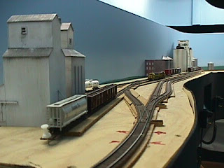
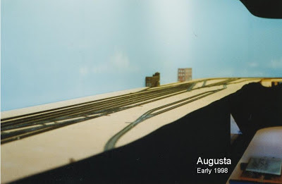
Work progressed almost every night of the week and so it did not take very long to get to the stage shown in these two images.
More next time.
Rod.


02/01/2013

A new layout


The new layout gets started.

      I started a new career in 1988 and this gave me the opportunity to visit our head office in Chicago with the first visit in 1989. I met up with a fellow who has since been a good friend who took me to many of the railroad hot spots around the city. I also had the opportunity to meet the Reid Brothers of Cumberland Valley Railroad fame and Bill Denton. Bill took me to his home for a pizza and to visit his basement layout. Boy was I impressed with his track work and hand laid turnouts. The track was Micro Engineering Code 55 and it looked outstanding and straight away I knew that I wanted to use it one day.
     It wasn't until 1994 that I got to visit my first N Scale Convention in Portland with a few good friends. While we were strolling around the numerous manufacturers stands I noticed that ME had just announced the release of their Code 55 #6 turnouts in N Scale. Now this set my head spinning, I had a decent running layout but it was just lacking something. I had seen the Code 55 track at Bill's and this just kept coming back into my head.
     Back home and watching a car race that was not going too well on TV I decided that my existing layout had to go and I should build a much better operating layout that would suit my new needs and of course use this new Code 55 track. So by that Sunday evening it had gone, all of the scenery was in ten plastic bags out the front of the house and the salvaged L Girders was all over the floor.
     It did not take too long to measure up the room and work out what was to be my dream layout.

This is the plan

This track plan is the start of the new Santa Fe Railway Southern Division.
 
     There was a long way to go and little did I realize at the time, that several of my friends were upset at me tearing the layout down for as they have since told me that at the time I was the only one with an operating layout.

To be continued.
Rod.